New WIP Car Chassis - Feedback wanted!

This might be of some use; it’s the (paraphrased) code I used to make the torque curves 'n stuff I posted above. It might give an idea of the number of parameters used to “predict” the performance.

The total drag on the car (in kN) is given by the equation below (where veh_speed is the speed of the car in m/s at any given point, A is the frontal area taken as the height*width, Cd is the drag coefficient, generally about ~0.3 for a standard family car, decreasing down to ~0.05 for a top-end supercar, and rho is the density of the air, ~1.225 kg/m^3. “ad” is the drag due to the surface the tyres are in contact with, and is a figure roughly between 0.01 and 0.3)
I’m aware I haven’t said what bd is; that’s because I don’t remember, and have to wait to download MatLab again so I can check in the actual file.

Total_Drag = (VehicleMass+DriverMass)*gravity*(ad + bd*veh_speed)+1/2*rho*A*Cd*veh_speed^2

The maximum power available from the engine at any given point is calculated by several equations.
Number 1 (where EngineSpeed is the current base engine speed in rpm; i.e. what the crankshaft is rotating at).

EngSpdRad = EngineSpeed*2*pi/60

Number 2 (unfortunately I don’t have the code for the torque map, it was produced using a seperate program I didn’t write :confused:
X-axis is engine speed in rpm, Y-axis is Nm)

EngPower = EngSpdRad*EngineTorque

Then, taking the largest value from the previous calculation,

CurrentTractiveEffort = maxPower/veh_speed

(Now, bare in mind that this value is not the actual tractive effort figure; we haven’t discussed gears yet…)

So, moving onto the actual fun stuff…

In this calculation the EngineTorque is the current torque the engine is producing. As I don’t know quite how this is calculated I can only suggest you set the torque to a figure roughly based on the Y-axis figures in the image above, given the current engine speed (in rpm).
(FinalDriveRatio is a figure generally between 3 and 5, GearRatios[i] will be a table of ratios; I can’t check what figures they are until I’ve downloaded MatLab again, which I’ll try do overnight. Yes, overnight… It’s a 2GB file and our internet is <2mb/s… RollingRadius is [I think] simply the radius of the tyre)

for i = 1,6 do
    TractiveEffort = (EngineTorque*FinalDriveRatio*GearRatios[i]*transEfficiency)/RollingRadius
    veh_speed = EngSpdRad/GearRatios[i]*FinalDriveRatio*2*pi*RollingRadius/60
end

Here are a few images that might be of additional use to see standard torque and power curves against vehicle speed (taken from my course documents).


Hope all this help a bit and doesn’t just add confusion lol

3 Likes

Thanks! Don’t understand it fully yet, but should help.

Updates have been made! See edited first post!

I’ve obtained a speed time curve:
On a default baseplate:


On the Test Track

The car seems to bounce around lots on the test track but not on the default baseplate, which is odd as they should have the same Elasticity.

Edit:


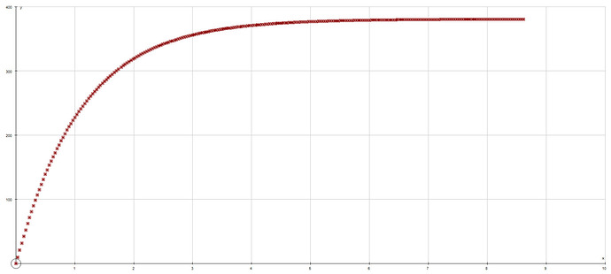
This is in MPH against time in seconds. The 0-60 is incredibly fast, yet the car can barely break 100, and even my little compact can make it to that speed. I’m not introducing any frictional forces myself in this test, no air resistance, so I’m sort of at a loss of what to do here.

How are you generating power? Are you using one of the bodymovers?
If so that could account for some of the issues; I’ve tried to use them for vehicles before and found them rather unreliable, and more than a tad difficult to try convert the units.
The curve follows a fairly standard shape, but the reason the first region is so fast is due to the physics applying the max torque instantly. If you set up a table of torque figures based on vehicle speed then it should show a more natural curve. Also, as I guess you don’t have a clutch modelled (yet… ;)) ideally the torque should have a base value of ~80 (Nm) between 0 and 10mph.

i.e.

torque = { 
    	s0  = 80, --*10Nm
        s10 = 10,
        s20 = 23,
        s30 = 30,
        s40 = 33,
        s50 = 32,
        s60 = 31,
        s70 = 29,
        s80 = 26,
        s90 = 23
}

while wait() do
    local speed = math.ceil(vehSpeed/10)*10
    local speedL = math.floor(vehSpeed/10)*10
    local upper = torque["s"..speed]
    local lower = torque["s"..speed-10]
  	vehicle.MotorTorque = (lower+((vehSpeed-speedL)/10)*(upper-lower))*10 -- Interp the torque points   
end

EDIT: I’m aware this is totally the wrong way around to do the torque calculations but it kinda works lel

1 Like

The wheels have two parts with BodyThrust in them, which generate the torque. Is there an equation I can use that links the torque sent to the wheels, the engine RPM, and vehicle speed?

Edit: Found the problem. This is a graph of WheelRPM against time with a constant torque applied and all collisions off

It should be directly proportional, but instead there’s a huge friction being applied despite no collisions and so nothing to generate friction with.

Power = EngineSpeedInRadiansPerSecond*CurrentTorque

To get rid of what appears to be wheel inertia (?) just make the density 0.01 and make a part in the chassis somewhere to add the extra weight. Maybe that’d work? What kind of joint are you using? It might be a good idea to switch to the new HingeConstraint (I think you mentioned above that it’s just a standard old hinge?)

Also, unless you already have, I’d suggest giving BodyAngularVelocity a try… maybe that’d solve a few issues or at least make it more straightforward.

BTW, I realised it’s probably better to interpolate the motor torque against engine speed (rpm), not the vehicle speed lol.

EDIT: how the heck did I reply to myself…

@madattak

1 Like

engineSpeed = wheelSpeed*gearRatio
torque = TorqueCurve(engineSpeed)*gearRatio

more complicated on auto because torque converter.

Torsion via BodyThrusts works well for me, so it’s probably not the cause of the issue. If the wheel has a high moment of inertia it wouldn’t cause drag and would probably keep the car in motion (if anything).
Yeah, HingeConstraints will be ideal when they’re released.

That’s what I use currently

But wouldn’t this just result in even less torque at high speed, making the problem worse?

I think I’m just going to wait for new constraints then start again from there.

Oh, that’s probably your issue. Glue tends to work better than hinges atm.

“Less torque at high speed” is perfectly natural, but tbh that equation is pretty much useless taken out of context. Probably better to ignore it lel

Yeah, they don’t wobble much which is great, but they seem to experience absurdly high friction, which I think is why the acceleration from 0-60 is F1 speed yet the car is incapable of breaking more than about 120.

We haven’t encountered those sorts of issues at Suspension Test, which is why I’m dubious that it’s the fault of physics. You can try printing the torque that’s being delivered to the wheels every frame and see where that takes you.

at least now you have a good electric car.

The graph I posted earlier is just a wheel on a hinge, with two parts with body thrust in welded to it. The body thrusts are constant, all friction is 0, all collisions are off. It should be directly proportional, a=F/m , f and m are constant, but it tapers off quickly, showing some sort of string frictional force.

Hinges are unstable at high speeds and torques. Have you done the same test with glue?

Am I doing something wrong? It wont move, and if I ramp the power up it still wont move until the wheel flys of completely.

Try messing around with the glue’s face values.

I’ve added an ABS system for the brakes, updated the gear ratios, and fiddled with the power and friction. I’ve tried to counter the weird extra friction in the hinges with an extra force, which mostly works but needs a little extra tuning. The cars now do 0-60 in 8 seconds and max out at 120, instead of 0-60 in 2 seconds and max out at 100, which only RallyX cars do.
However the cars don’t have enough torque, tractions fine, to get up anything other than a shallow hill. I’m thinking it’s because I’m treating my cars as full size but the default roblox gravity is for cars measured in cm not m?

@NWSpacek @Fractality_alt
Did some tests and cylinders are definitely not real cylinders: At about 120MPH cylinder wheeled cars will start to jump around uncontrollably, but using ball wheels results in a perfectly smooth ride at all speeds.

3 Likes

that’s problematic. would you mind filing a bug report?