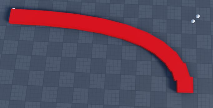
Cylinders will produce perfect results. The OP is just needs to do it with toworldspace.
This?
        cyl.CFrame = cf:ToWorldSpace(
            CFrame.new((line.Size * Vector3.new(0, 0, 1) / 2))
        ) * CFrame.Angles(0, 0, math.rad(90))
I’m not sure how your code works, but no.
More like
cyl.CFrame = cf:ToWorldSpace(CFrame.new(line.Size / 2))That wouldn’t work because adds the Y size to the CFrame.
That would require too much maths because I’m doing it on real time with code.
Then make it use the X size? I don’t see this being too complicated.
OH I see what your doing! So your doing it by dividing the line between two points, but in reality, you need to get the PART x size and divide it by two, then use toworldspace with that.
That’s what I’m doing with this code
I’m multiplying the size X and Y by 0 and only the size Z would act here
Can you send me the updated code your using?
This is the current code to generate the parts, I’ll code an entire module to create conveyors, that’s why I don’t like irregularities and that’s why I don’t like using cylinders because I will use stretched models instead of BaseParts.
local function QuadraticBezier(t,p0,p1,p2)
    return (1-t)^2*p0+2*(1-t)*t*p1+t^2*p2; --<Very simple :D
end;

local origin = workspace.Part1
local curve = workspace.Part3
local goal = workspace.Part2

local steps = 10

local function GetDistanceOfCFrames(cf,cf2)
    local axis,theta = cf:ToAxisAngle()
    local axis2,theta2 = cf2:ToAxisAngle()
    return (cf.Position-cf2.Position).Magnitude,((axis*theta)-(axis2*theta2)).Magnitude
end

for i = 0, steps-1 do
    local pos = QuadraticBezier(i/steps , origin.Position, curve.Position, goal.Position);
    local pointfront = QuadraticBezier((i+1)/steps, origin.Position, curve.Position, goal.Position)

    local cf = CFrame.lookAt(
        (pos + pointfront) / 2,
        pointfront
    )

    local mag = (
        pos - pointfront
    ).Magnitude

    local line = Instance.new("Part", workspace)
    line.Anchored = true
    line.Size = Vector3.new(4, 1, mag)
    line.BrickColor = BrickColor.new("Really red")
    line.CFrame = cf
    line.TopSurface = Enum.SurfaceType.Smooth
    line.BottomSurface = Enum.SurfaceType.Smooth

    if i > 0 then
        local cyl = Instance.new("Part", line)
        cyl.Anchored = true
        cyl.BrickColor = line.BrickColor
        cyl.Size = Vector3.new(1, 4, 4)
        cyl.CFrame = (cf * CFrame.new(0, 0, line.Size.Z / 2)) * CFrame.Angles(0, 0, -math.rad(90))
        cyl.Shape = "Cylinder"
        cyl.TopSurface = Enum.SurfaceType.Smooth
        cyl.BottomSurface = Enum.SurfaceType.Smooth
    end
end;
I’m really sorry, not sure why this is happening. I’m working on my own project right now so I can’t dive deeper into this. Hope this gets fixed!
I’m not saying to use cylinders at all. If you take the rectangle parts and move them on their local x-axes by half their widths towards the interior of the curve, you get no gaps.
The cylinder idea is smart, and will work for small scales, but will not work for bigger parts because the roblox cylinder is actually a pretty low-poly prism, so it’s got big flat sides.
I think you should try increment your alpha to something smaller so the gaps can be filled. So basically increase the steps.
The problem is that the size and gap size aren’t constants.
I can’t increment it, need to be from 0 to 1
No gaps but now it looks like random positioned parts.

This is the best I got

But as you can see, now the problem here is the Vector Z, I don’t know what I need to add to remove that uncomfortable irregularity
This is the current script
    local pos = QuadraticBezier(i/steps , origin.Position, curve.Position, goal.Position);
    local pointfront = QuadraticBezier((i+1)/steps, origin.Position, curve.Position, goal.Position)
    local superfront = QuadraticBezier((i+2)/steps, origin.Position, curve.Position, goal.Position)

    local cf = CFrame.lookAt(
        (pos + pointfront) / 2,
        pointfront
    )

    local cf2 = CFrame.lookAt(
        (pointfront + superfront) / 2,
        superfront
    )

    local magnitude = (pointfront - pos).Magnitude

    local bound1 = cf + cf:VectorToWorldSpace(Vector3.new(2, 0, -magnitude/2))
    local bound2 = cf2 + cf2:VectorToWorldSpace(Vector3.new(2, 0, magnitude/2))
    local boundsMag = GetDistanceOfCFrames(bound1, bound2)

    local line = Instance.new("Part", workspace)
    line.Anchored = true
    line.Size = Vector3.new(4, 1, magnitude)
    line.BrickColor = BrickColor.new("Really red")
    line.TopSurface = Enum.SurfaceType.Smooth
    line.BottomSurface = Enum.SurfaceType.Smooth

    line.CFrame = cf - cf:VectorToWorldSpace(
        Vector3.new(boundsMag * math.pi, 0, 0.5)
    )
I don’t know if anyone alreaady said this but you could try dividing the lookvector so that it doesnt fully move outside of the previous part
I think I solved it using this code
local magnitude = (pointfront - pos).Magnitude

local bound1 = cf + cf:VectorToWorldSpace(Vector3.new(2, 0, -magnitude/2))
local bound2 = cf2 + cf2:VectorToWorldSpace(Vector3.new(2, 0, magnitude/2))
local boundsMag = GetDistanceOfCFrames(bound1, bound2)

magnitude += math.atan(boundsMag) + 0.1 -- This exact line using 'math.atan'.
These small gaps that I left empty are because the parts that make the line are only 10 to make it friendly to poor specs computers.
Anyways, thanks for the help @RunKittenzRComin and @nicemike40
