I’m trying to understand the mechanism, and this is what I’ve got so far:
The red-marked parts are rigidly connected, and the blue-marked parts are rigidly connected. The “blue” assembly moves up and down by sliding “inside” the cylinder on the red assembly, using a combination of a PrismaticConstraint to keep the movement parallel to the red cylinder, a Spring to dampen the movement and a Rope to limit the movement.
The two “arms” on the left are rigidly connected to their corresponding assemblies, but are connected to each other with a Hinge. I expected that hinge to be perpendicular to the travel of the “piston in cylinder” mechanism, but it’s actually on a weird angle like this:
That doesn’t seem right, let me know if I’m misunderstanding.
Even if that hinge worked as I expected, the mechanism would be completely constrained! I.e. there should be no way for it to move. The mechanism is essentially a triangle. For the mechanism to move as expected, the long side would have to get longer and shorter. Since the two over edges cannot change lengths, the only way for that to happen is if all three angles in the triangle can change freely. That means there would have to be Hinges where I put yellow dots in the drawing. The two “arms” would still have a purpose, keeping the wheels from rotating on the vertical axis.
Removing the arms and extending the wheels fully, it looks like so:
It seems the movement of the blue assembly isn’t parallel to the red “cylinder” assembly. Selecting the attachments of the PrismaticConstraint, it seems like they’re at an angle which could explain that. Inspecting the Orientation of these attachments reveals that they’re off from increments of 90 by a couple of degrees
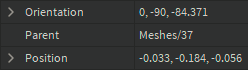
Manually setting it to the nearest increment of 90 makes it parallel:
But it’s still offset a bit to the side, i.e. the piston and cylinder aren’t colinear / on the same line. This is due to the attachments of the various parts being offset in all sorts of weird ways. Zooming in using a low Field of View, you can clearly see how things are misalinged in the original model you sent:
I tried adjusting them to get them lined up, but didn’t get a perfect result. If you want to get it perfect, I suggest redoing some of the subassemblies, using the Properties window to manually type in numbers to get things perfectly aligned when e.g. trying to get things in the center of another thing.
Here’s the landing gear with the changes I talked about:
landing_gear_improved.rbxm (1009.0 KB)
I think the issues came up because you’ve been using the constraint button to place constraints and attachments with the mouse. This can sometimes be okay if your parts are sized in a way that the move increments can make sure that things are placed e.g. in the center, but with your complicated / non-flat meshes with weird angles and sizes, it’s better to align things manually by typing in numbers.


