Context: I’m scripting a road creation system and am currently working on curved roads using Quadratic Bezier Curves. The curved roads in question are using cage meshes and positioning 9 bones along the curve. My problem is that due to the bones in the middle tugging on the 2 ends, the mesh wont line up properly to the bones on the ends.
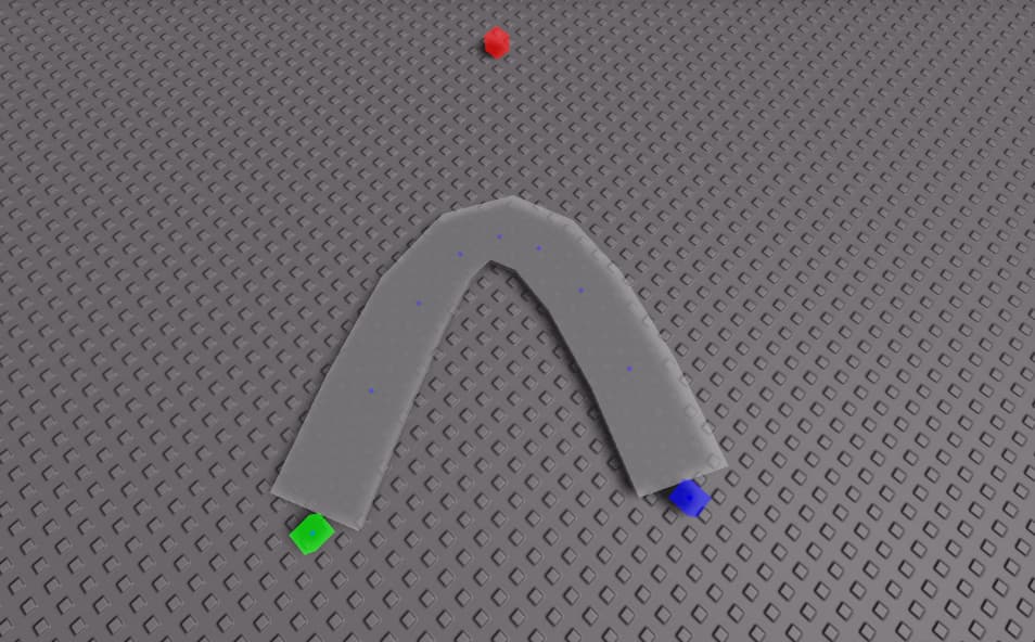
Here is an image of the issue:

As you can see, the edges - especially the left one - do not align perfectly with the bones. This issue is better seen with a larger turn.
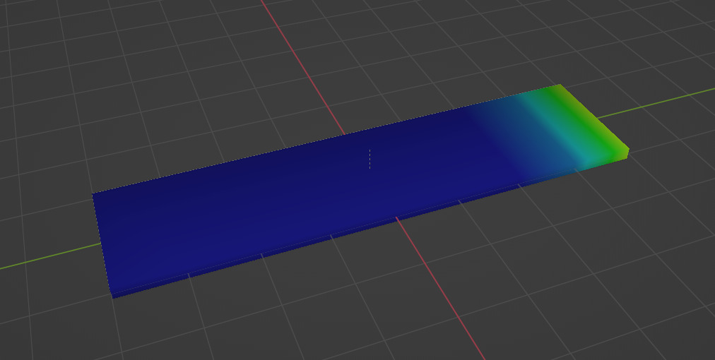
Here is an image of the weight paint which I have set to auto:
Here’s my script if that will help although it is perfectly functional and I believe the issue is with the mesh weights.:
local RoadHandler = {}

local workspace = game.Workspace
local curve = workspace.curve
local road = workspace.Road.RoadMesh
local points = workspace.points
local ServerScriptService = game:GetService("ServerScriptService")
local RoadModule = require(ServerScriptService.RoadModule)


local function CalculateRoadMeshZ(segments)
	--[[local mag1 = (points.p2.Position - points.p1.Position).magnitude
	local mag2 = (points.p3.Position - points.p2.Position).magnitude

	road.Size = Vector3.new(road.Size.X, road.Size.Y, mag1+mag2)]]
	local totalmag = 0
	local lastpos = nil

	for i,v in pairs(segments) do
		if not lastpos then
			lastpos = v
		else
			totalmag += (v - lastpos).Magnitude
			lastpos = v
		end
	end
	road.Size = Vector3.new(road.Size.X, road.Size.Y, totalmag)
end


local function postionBone(p0, p1, num)
	local direction = (p1 - p0).unit
	local pos = p1
	local number = tostring(num)
	local bone
	print(num)
	bone = road:FindFirstChild("Bone.00" .. number+1)
	bone.CFrame = CFrame.new(pos, pos + direction)
end

local function lerp(a, b, c)
	return a + (b - a) * c
end

local function quadratic(p0,p1,p2,t)
	local l1 = lerp(p0, p1, t)
	local l2 = lerp(p1, p2, t)
	local quad = lerp(l1, l2, t)
	return quad
end

--[[
local function quadratic(p0, p1, p2, t)
	return (1 - t)^2 * p0 + 2 * (1 - t) * t * p1 + t^2 * p2
end
]]

local function createBezierSegments(p0, p1, p2)
	local segments = 8
	local segmentLength = 1 / segments

	local SegmentTable = {}

	for i = 0, segments do
		local t1 = (i - 1) / segments
		local t2 = i / segments

		local pointA = quadratic(p0, p1, p2, t1)
		local pointB = quadratic(p0, p1, p2, t2)

		table.insert(SegmentTable, pointB)

		postionBone(pointA, pointB, i)
	end
	return SegmentTable
end

function RoadHandler.createBezier(p0, p1, p2)
	local Segments = createBezierSegments(p0, p1, p2)
	CalculateRoadMeshZ(Segments)
end

return RoadHandler
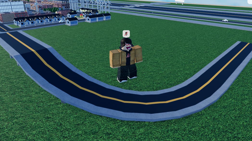
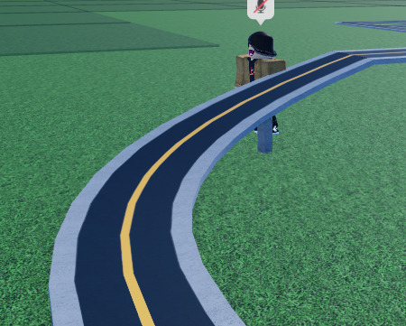
This has been quite annoying to figure out and I’m not sure if there is a solution. I think some games like Mini Cities 2 implement this system perfectly. Eventually, I hope to get my roads looking like this:
I really appreciate anny help or advice on this subject.
