Hey! I’m attempting to recreate the effects of the resize align plugin with parts in a live game. I’m using pathfinding waypoints currently to create parts that follow the path using the code below
local Points = Path:GetWaypoints()
			for i, Point in pairs(Points) do
				local Part = script.Waypoint:Clone()
				local NextPoint = Points[i+1]
				if not NextPoint then
					continue
				end
				local vector, vector2 = Rotation*Point.Position, Rotation*NextPoint.Position
				local Point1, Point2 = Vector3.new(vector.X, 1, vector.Z), Vector3.new(vector2.X, 1, vector2.Z)
				local distance = (Point1-Point2).magnitude
				Part.Size = Vector3.new(40, 0.1, distance)
				Part.CFrame = CFrame.new(Point1, Point2) * CFrame.new(0, 0, -distance/2)
				Part.Parent = Folder
			end
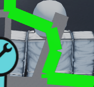
However, this allows for blatantly visible gaps at the points where parts intersect, rather than a seamless connection of edges. I know I need to achieve effects similar to that of the resize align plugin, but I’m unsure of the mathematics required to make that happen. How can I resize/align each part to seamlessly connect?
Sure! Here is my current result.
vs. a crude mockup of my intended result
What I’m looking for is similar functionality to the Resize Align plugin by Stravant. The faces at the end/beginning of each part should be able to line up without the visible gaps. What is the math required? I can pretty easily do everything else, such as determining which parts need to connect at which ends, etc… it’s just the actual concept of how to determine where they should meet relative to their desired starting/end point that is confusing me
Edit:
Here is the current code I’m using to achieve the result I currently have.
			local Points = Path:GetWaypoints()
			for i, Point in pairs(Points) do
				local Part = script.Waypoint:Clone()
				local NextPoint = Points[i+1]
				if not NextPoint then
					continue
				end
				local vector, vector2 = Rotation*Point.Position, Rotation*NextPoint.Position
				local Point1, Point2 = Vector3.new(vector.X, 1, vector.Z), Vector3.new(vector2.X, 1, vector2.Z)
				local distance = (Point1-Point2).magnitude
				Part.Size = Vector3.new(40, 0.1, distance)
				Part.CFrame = CFrame.new(Point1, Point2) * CFrame.new(0, 0, -distance/2)
				Part.Parent = Folder
			end
Are the parts meeting at their centres on their ends? Because if the are then you can define a triangle from half the length of the edges and then find the other length with the cosine law.
Basically, if the both intersect on their X size vector, the lengths of the triangle are partA.Size.X/2 and partB.Size.X/2 and then the angle between them is the CFrame vector that defines its orientation, so ideally the lookvector. Basically you can get the angle between two vectors with something called the dot product formula which is a.b=|a||b|cosθ
Now that you have 2 faces and an angle, you can solve for the face opposite to the angle using the cosine law, which is c^2 = a^2 + b^2 - 2ab cosθ
This will be the side of the triangle that connects the two sides that arent connecting. Also the nice thing about dot product is it always finds the internal angle of the vectors so you dont have to worry about it trying to make a triangle on some weird other side if you define the proper edges as the vectors you’re working with.
Another note is that you can define these vectors by getting the unit vector of the direction vector, which by default is what a cframe lookvector should return, then multiplying that by the scalar coefficient that is the half size side of the triangle that I was talking about.
This should give you your size, direction, etc of what you need!
Hopefully this helps, sorry it got so mathy.
Also here is a visual since I asked you for one.
If at all possible, I would like to avoid the creation of more parts than I currently do, which is why I’m seeking to resize the parts so that the outside edges (Where the gap is currently visible) meet perfectly.
I believe achieving this result should be rather simple, as the only real variable needed to be adjusted is my current calculations for length (which is currently solely magnitude). I’m just not great with geometrical programming and don’t know where to even begin.
I assume it involves calculating each corner of the leading and trailing ends of both parts and calculating a new size for both parts that will cause the 2 outside corners of both to meet at the same vector. How to do either of these things, however, I’m frankly clueless.
Basically you can define a vector in 3-space by the point which it starts at plus the direction vector times some scalar value. The point of intersection of two 3-space vectors may be found by setting them equal to eachother and solving for a point.
The way to compare the lines is with parametric equations generally, and this allows you to make systems of equations to solve for the variables in the system. Not completely sure how the computer would do non comparative math like that but thats the challenging part that I think you’ve got.
Once you have the point of intersection you can check the distance along the vector that those points are and add that to their corresponding parts size value. Thing is youll have to only add the size in that direction to that side of the part or else it would really mess up other connections.
Here is an example of solving the poi of two lines in 3 space.
when you make a part to compensate for the skew or parallel case, I am fairly sure you can just make a filler part in a very not super mathy way that isnt as insane as this is. so parallel and skew will actually be easier ideally.
P.S. these vectors are also defined by a scalar size value, probably unrelated to the part to make sure they intersect and the lookvector idea I mentioned earlier should give them a direction in 3 space. Also note you dont have to make these vectors at the actual position but you could just mathematically define them and find the distances you have to travel from here you defined their start to find the end point that the rectangles need to be in terms of size.
I don’t think I’m versed enough to understand a word of this but I appreciate the response. I’ll mark it as the solution because I don’t doubt the accuracy but whether or not I will be able to execute this is another story LOL
No problem whatsoever, seriously, if you happen to need more help my discord is Ethanaut and I could walk you through what I was explaining in a vc or something. It is really hard to convey this stuff over text. Also try geogebra, it is a 3D calculator that will visualize this stuff for you!