I’m trying to make a drill, not a handheld one but the kind you drive, (AKA a subterranean vehicle) and so when I rotate the drill in front of the vehicle, it rotates but not how I’d want it to:
(I drove in a circle on purpose, the bug is that it doesn’t rotate with the vehicle turning)
This is the script I created, it’s parent is the drill part:
local part = script.Parent

local incr = 360/20

while true do
	for deg = 0, 360, incr do
		part.Rotation = Vector3.new(90, deg, 0)
		wait()
	end
end
Does anyone know how I could change this so that it rotates with the rest of the vehicle? I’ve tried a lot of different solutions and I know why this example doesn’t work but if I change the x and z angles of the Vector3 to part.Rotation.X and part.Rotation.Z it still doesn’t work.
I’ve tried that too, that makes the vehicle do a billion backflips. Because the part has got a weld constraint so if I change its cframe everything else changes too.
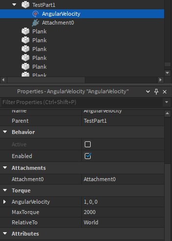
AngularVelocities have 2 main properties which determines the direction/speed of how the part rotates.
The AngularVelocity is the speed at which the part rotates, and MaxTorque is the maximum speed that the part can rotate at
I’m not sure if the velocity rotates relative to the part’s rotation, or if it rotates along global rotation. You can do some messing around with the properties if it interests you at all. If the velocity rotates relative to the part’s rotation, you can just put in something like (3, 0, 0) for the AngularVelocity
If the velocity rotates relative to the global rotation, you might have to do something like this:
Part.AngularVelocity.AngularVelocity = Part.CFrame.rightVector * Speed
`` rightVector is similar to lookVector, in the sense that it stores the direction that the part is looking at
I’m just now realizing that you can change the RelativeTo property to Attachment0 and it should rotate according to the part’s current rotation, meaning all you have to do is this:
Velocity is physics-based though, so that means there will probably be a visible smooth motion when it tries to rotate to match the rest of the vehicle.
How is the vehicle moved?
If you move it using physics why not just use a HingeConstraint? You can set it to Motor, and change the AngularVelocity for your speed.
If you don’t want the drill to make the vehicle spin when it hits something then you can just weld a transparent CanCollide true cone the same size as the drill to the vehicle, then make the drill CanCollide false so it can spin freely. Make it Massless as well so it doesn’t affect the movement of the vehicle.
The vehicle uses the car script from the jeep in the race template, so I imagine it’s moved by physics. What do I put in attachment 0 and 1 for the hinge constraint? Also, am I right in saying I should parent it to the drill?
Go to your Constraints tab in the Model tab up top.
Select View Constraints and Show on Top in the tools.
Select Hinge from the drop down menu icon.
Click the vehicle chassis Part or Union you want the drill attached to, then click the drill bit.
A HingeConstraint will be added to the first item you choose, as well as an Attachment in each one.
There will be 2 green spheres showing where the Attachments are, and their orientation will be displayed as yellow arrows and orange arrows when you select them.
The Position values of the drill Attachment won’t be at 0,0,0 since you used the mouse to select it, but manually set it to 0,0,0 in the Properties window.
Set the Orientation of the Attachment so the yellow arrow points at the drill tip. Set the orange arrow pointing up (not important, but just for this example).
Set the Orientation of the other Attachment to be the same as the drill Attachment.
Now select the drill’s Attachment and copy the WorldPosition of the Attachment.
Select the other Attachment and paste that value into its WorldPosition so that both Attachments are in the same Position.
Now you can make the MotorMaxTorque of the Hinge a very large number, and you can manually change the AngularSpeed to whatever value you’d like (it’s in radians/second). If you want to be able to change the speed of rotation in game you can script the AngularSpeed to whatever you want there.
Thanks, that works. While you’re here, do you know how to change where the camera is focused when you’re sitting in the vehicle seat? I think by default it makes you look at the centre of the model.
As far as I know the VehicleSeat is the camera focus, but I could be wrong. Just for a test move the seat 10 studs to the side to see if it affects the view.
I just tested it out, looks like it does look at the centre of the vehicle. I’m sure there must be a way to manipulate the camera, hopefully I don’t have to script it though.